latest news
NS ICNG now for sale.
![[menu logo]](../images/christrainslogodot.png)
NS ICNG now for sale.
Want to start or grow your collection by more than one product? Use these coupon codes for bulk discounts:
GIMME2 = 10% off two products
GIMME3 = 15% off three products
GIMME4 = 20% off four or more products
Subscribe to the mailing list for occasional updates and important announcements.


With the advent of the MSTS gamepack for gMAX, there's some things you need to know which supercede the rest of this FAQ.
I reckon the default user interface that the MSTS gamepack sets up was designed by a one-armed blind man. It's revolting, and totally out-of-form if you're used to using 3DSMax. You can, however, change all that. Like 3DSMax, gMAX allows full customisation of the user interface. I won't go into it all here, but this little tip will at least give you a more 3DSMax-like interface.
Once you've installed the gamepack, look in the folder (g-maxINSTALLEDFOLDER)\gamepacks\TrainSim\Scripts\Startup. You're looking for the file called startup.ms. This is a plain-Jane text file. Open it in your favourite text editor. At the bottom is a section like this :
-- Load UI files --
try (
colorMan.loadColorFile (getdir #maxroot + "\gamepacks\\TrainSim\\UI\\Trainsim.clr")
actionMan.loadKeyboardFile (getdir #maxroot + "\gamepacks\\Trainsim\\UI\\Trainsim.kbd")
menuMan.loadMenuFile (getdir #maxroot + "\gamepacks\\Trainsim\\UI\\Trainsim.mnu")
cui.loadConfig (getdir #maxroot + "\gamepacks\\Trainsim\\UI\\Trainsim.cui")
quadMenuSettings.loadSettingsFile (getdir #maxroot + "\gamepacks\\Trainsim\\UI\\Trainsim.qmo")
) catch (
messageBox "An error occured trying to load the TrainSim UI files."
)
To get a more Max-like interface, comment out a couple of those lines using '--' to comment them (in red, below):
-- Load UI files --
try (
-- colorMan.loadColorFile (getdir #maxroot + "\gamepacks\\TrainSim\\UI\\Trainsim.clr")
-- actionMan.loadKeyboardFile (getdir #maxroot + "\gamepacks\\Trainsim\\UI\\Trainsim.kbd")
menuMan.loadMenuFile (getdir #maxroot + "\gamepacks\\Trainsim\\UI\\Trainsim.mnu")
-- cui.loadConfig (getdir #maxroot + "\gamepacks\\Trainsim\\UI\\Trainsim.cui")
quadMenuSettings.loadSettingsFile (getdir #maxroot + "\gamepacks\\Trainsim\\UI\\Trainsim.qmo")
) catch (
messageBox "An error occured trying to load the TrainSim UI files."
)
Now you won't have the happy, shiny, playskool interface that comes with the gamepack, but a more down-to-earth, 3DSMax-like interface.
Unlike the conv3ds converter, gMAX doesn't have the naming convention limitations that you have problems with in 3DSMax. That still doesn't mean the original MSTS manual is correct though. Here are the correct names for the parts that you should use in gMAX:
PantographTop1A, PantographTop1B, PantographMiddle1A, PantographMiddle1B, PantographBottom1A, PantographBottom1B, WiperArmLeft1, WiperArmRight1 etc. etc.
The documentation for the LOD editor isn't particularly clear on how you create LODs. As I discovered, if you get it wrong, gMAX unmercifully crashes and corrupts the data in the process meaning you have to re-load and start again. So here's a step-by-step guide - it actually turns out to be pretty easy.
If at some point you decide you've removed too much from the lower levels of detail, click the "-" symbol to delete it from the LOD structure. The LOD manager will move you back to the next highest LOD to start again.
Note: The more LODs you put into a model, the longer it takes to export. This shouldn't matter but if you have a slow PC, it could increase the amount of time you're left sitting around waiting. At least the export function has a progress bar that shows you that it's still working and hasn't crashed your machine.
Blurry textures can be eliminated using the gMAX trainsim pack - the material editor allows you to set the MIP level directly. I set all mine to a MIP BIAS of -3. The manual tells you that values between -5 and +5 are allowed. The higher the number, the more blurry the texture, but the less it will alias in the distance (the jaggy, swimming lines effect you get in the distance).
The 3rd wheel problem described in the rest of this FAQ appears to have been solved by the MSTS gamepack plugin for gmax so you shouldn't see this problem again.
Very often, when you use Alpha maps for train windows, everything is fine until you try to look at the scenery through the other side of the carriage. Trees and fences disappear. This is because of the sort order of the alpha maps.
gMAX provides a neat way around this. You need to split out the inside windows and outside windows of your carriage or engine into their own objects. These two object then need to be attached to the MAIN object in the same way you'd attach a bogie, or pantograph part. The difference is that gMAX will allow you to collapse those items back into the MAIN object when it exports to the .s shape file.
To do this, set the object/subobject flags as follows:
inside:: collapse node, SubObject ID=2, 'Sort this subobject' and Sort Priority=15
outside:: collapse node, SubObject ID=1, 'Sort this subobject' and Sort Priority=5
I tried the example file that came with gMAX (the Deltic55 - crap model, by the way) and it had different subobject IDs for the inner and outer windows, as indicated above, but they were the other way around. In some cases, the inner windows vanished, and in most cases, you couldn't see trees or fences when looking all the way through to the other side. By playing with the settings for a while, I found that the above solution worked on all my trains and coaches. I hope the same works for you.

If you're editing the .s shape files for any of the following operations, use wordpad, rather than notepad. Wordpad understands the unicode format, notepad doesn't and will mess up the files. Alternatively, get a good third-party editor like Textpad (www.textpad.com) which can auto-sense the various text formats, and allows direct editing of unicode files.
The answer is here, but it's in Dutch at the moment. I'm going to do my own English version shortly.The Link
Perhaps the most asked question is this : I've built 3 wheel sets on my bogie and named them correctly, but the third set drags - it won't spin around. Why?
Well - I know why. It's to do with the ordering of certain items in the .s shape file. Even if you build the model absolutely correctly inside 3DSMax, you'll never see that third set of wheels spinning unless you edit the shape file. There's two sections you need to check.
First of all, it's worth pointing out that you need to ensure the orientation of the pivot point in 3DSMax is correct - if it isn't, all manner of nastiness can happen with your wheels:
Firstly, open your shape.s file and look for the first instance of your wheels - 'wheels13' is what you're looking for. It will appear in a block of code like this:
	matrix BOGIE1 ( 1 0 0 0 1 0 0 0 1 -0.00100048 0.527461 4.44794 )
	matrix WHEELS11 ( 1 0 1.60131e-024 0 1 0 -1.60131e-024 0 1 -9.35444e-008 0.0638839 2.3928 )
	matrix WHEELS12 ( 1 0 1.60131e-024 0 1 0 -1.60131e-024 0 1 1.63326e-008 0.0638833 -0.120896 )
	matrix WHEELS13 ( 1 0 1.60131e-024 0 1 0 -1.60131e-024 0 1 1.19396e-007 0.0638832 -2.4787 )
	matrix BOGIE2 ( 1 0 0 0 1 0 0 0 1 -0.001 0.527461 -4.48235 )
	matrix WHEELS21 ( 1 0 0 0 1 0 0 0 1 -1.83138e-007 0.0638834 2.46397 )
	matrix WHEELS22 ( 1 0 0 0 1 0 0 0 1 -8.01895e-008 0.0638834 0.108795 )
	matrix WHEELS23 ( 1 0 0 0 1 0 0 0 1 2.98023e-008 0.0638832 -2.40753 )
Now look at that code again. You absolutely must have the bogies and wheels listed in the correct order. ie. BOGIE1 first, then WHEELS11, then WHEELS12 etc. If they're not in that order, rearrange the lines so they are.
Now go and find the second instance of WHEELS13 in your shape.s file. It will sit in a block of code that looks like this:
	animations ( 1
		animation ( 2 30
			anim_nodes ( 19
				anim_node MAIN (
					controllers ( 0
					)
				)
				anim_node BOGIE1 (
					controllers ( 0
					)
				)
				anim_node WHEELS11 (
					controllers ( 0
					)
				)
				anim_node WHEELS12 (
					controllers ( 0
					)
				)
				anim_node WHEELS13 (
					controllers ( 0
					)
				)
				anim_node BOGIE2 (
					controllers ( 0
					)
				)
				anim_node WHEELS21 (
					controllers ( 0
					)
				)
				anim_node WHEELS22 (
					controllers ( 0
					)
				)
				anim_node WHEELS23 (
					controllers ( 0
					)
				)
				anim_node PantographBottom1A (
					controllers ( 1
						tcb_rot ( 2
							slerp_rot ( 0 0 0 0 1 )
							slerp_rot ( 2 -0.104528 -1.99721e-016 -4.56908e-009 0.994522 )
						)
					)
				)
				anim_node PantographMiddle1A (
					controllers ( 1
						tcb_rot ( 2

etc etc etc ad nauseum
Read this carefully: Most of the time when you use conv3ds, it lists the bogies and wheels after everything else in this part of the file. So in my example, the first item would be MAIN, then the second would be PantorgraphBottom1A. If you want your third wheel to animate (and fourth, and fifth), the bogies and wheels must be listed in the correct order directly after the MAIN anim_node as shown in the above example. If they're not listed in this order, in this place in the file, you'll have those dragging wheels.
Interesting note: If you've tried to animate the third wheel by building it spinning with 8 frames, you'll get some extremely bizarre results. Remove the animation and try this fix I've shown here again and it should work.
In the techdocs, it tells you to name the various parts of the pantograph as PantoGraphTop1 etc. But when you convert this and try to run it, they don't animate. Well I've discovered why. conv3ds.exe truncates all entity names to 10 characters. When you convert a file with the names PantographTop1 and PantographBottom1 in it, they come out in the .s shape file as Pantograph and Pantograp0.
There's two types of pantograph. Single-arm and box-type. Both require slightly different techniques. The single-arm type is as documented in Kuju's techdocs. The box-type required a little reverse engineering to figure out because it's not documented anywhere.
Building single-arm type pantographs in 3DSMax:
††If you're using the new (Feb 2002) version of conv3ds, it does this renaming for you during conversion. I'm sure MS took the naming convention from my pages when they made this modification.....
This diagram shows the basic parts, how they're named in 3DSMax and how you need to rename them in the shape file in order for them to work:
Building box-type pantographs in 3DSMax:
††If you're using the new (Feb 2002) version of conv3ds, it does this renaming for you during conversion. I'm sure MS took the naming convention from my pages when they made this modification.....
This diagram shows the basic parts, how they're named in 3DSMax and how you need to rename them in the shape file in order for them to work:
Summary.
Link the pantograph elements as shown in the diagram below. Make sure the pivot points are all in the positions shown below too. Note that for the box-type, the 'A' and 'B' elements are not actually linked to each other.
How pantographs work.
All sections of Pantograph-1, if built on their own, will always go up and down on all copies of the model in a train set.
If you have two pantographs, then the Pantograph-1 sections will animate when that loco finds itself at the rear of a train set. The Pantograph-2 sections will animate when that loco finds itself at the front of a train set.
In the techdocs, it tells you to name the various parts of the wipers as WiperArmLeft1 etc. But when you convert this and try to run it, they don't animate. As with the pantographs, conv3ds.exe truncates all entity names to 10 characters. When you convert a file with the names WiperArmLeft1 and WiperBladeLeft1 in it, they come out in the .s shape file as WiperArmLe and WiperBlade.
Building animated wipers in 3DSMax:
I've cracked the blurry texture thing - properly, not using the "Point" hack. One evening I came home and looked at my models after changing the texture named_filter_mode in the shape files. I set it to "Point" instead of "MipLinear", and frankly wasn't satisfied. Sure the blurriness had gone in the distance, but at the cost of badly aliasing textures and the loss of the nice smoothing factor when I got up close. If I zoomed right in, I could see the individual pixels making up the textures. Not nice.
So decompiled one of the MS supplied models - the ACELA - into an editable shape file and then compared it to the ones I was getting out of conv3ds. This is what I found:
The minus number is a MIP multiplier, based on distance from the eyepoint:
The advantage is that the textures now don't go all fuzzy at a distance, but they maintain the MIP level smoothing when you're in close (which they don't when you use the 'Point' hack).
That negative number can also be positive but it pulls the MIP level in horrendously close. One other point : if you change the named_filter_mode to LinearMipLinear, you can get bilinear or even trilinear blending between the MIP levels. It all depends on what graphics card you have. This in combination with the MIP level entry means you actually have tons of control over the way the blurry textures display.
The real trick is to find a happy medium between non-blur and blur in the distance to get rid of the moire patterns (the weird speckling / cross-hatch type pattern). Bear in mind that what works on your graphics card might not work on others. Me? I'm using a crappy old Viper770 with the TNT2 chip on it and it looks great on there. I'm presuming that if an old card can look good, the newer cards will do my models more justice :-)
Thanks Steven Weller for letting me use his pictures as samples.
A lot of new modellers build their locos and carriages and assemble all the various elements of their textures into one 512x512 texture map. So one map carries the sides, front and back, roof and wheels all in one map. When they run the model in MSTS for the first time, in the distance, the train starts to go white and they don't understand why. Here's a detailed description of what is happening, why it does it, and how to get around it.
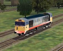
Above is a typical example. Up close, the textures work fine, but in the distance, all the surfaces start to get white edges. The reason for this is a combination of the way the texture map has been created, and the way the MSTS render engine deals with it. Here's an example texture:
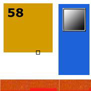
(Imagine that's a 512x512 texture). The texture has part of the side of the train, and a section containing a window. The rest of the texture is white. The black box outlines the section I'm going to talk about next.
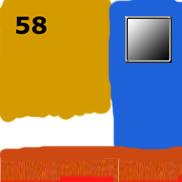
Imagine having a monitor which could only display 512x512 pixels. If you loaded a 512x512 texture map and displayed it, one texture pixel would correlate exactly to one pixel on the screen. Now as you move away from the texture, it occupies less screen space, yet your monitor has fixed-sized pixels. So what colour should each screen pixel be to try to maintain the look of the texture? Well this is what's known as MIP mapping textures - Multiple Image Pyramid textures. When you're moving away from the texture, the render engine needs to know what colour to make each pixel on the screen that that texture occupies. To do this, it creates progressively lower and lower resolution versions of your texture map - the multiple image pyramid - then it can refer to one of these levels when picking a colour for the screen pixel. Look at this example:
These are the top three layers of the MIP pyramid. Typically, the game engines will run this down to a texture which is 4x4 or even 2x2 at the lowest levels. You can see that for each level, the engine samples a 2x2 block of texture pixels from the next highest level. In this case, right away the nice tight yellow-to-white transition has blurred to a yellow-offyellow-white transition. The further it goes, the more that yellow part of the texture is going to become - well - not yellow. The example above shows Bilinear blending - the technical name for MSTS's "MipLinear" texture mode. You can also get game engines to do Trilinear blending - what MSTS calls "LinearMipLinear" which samples a 3x3 block rather than a 2x2 block.
So how to make your textures stay the correct colour for as long as possible? Simple - fill in the background with a colour that matches, or is closer to the colour you want:
|
 |
| Original texture | Modified texture |
Now when the game engine is calculating its MIP pyramid, your texture colours will be preserved further down the number of levels. Typically, you'd fill in the remaining white areas with a neutral grey too.
The result, is this:
Using the ffeditc_unicode utility, you can compress your shape files.
In the following examples, 'yourshape_in.s' is the shape file you get from running txt2uni, and 'yourshape_out.s' is the compressed binary version of the same thing.
To uncompress:
ffeditc_unicode.exe yourshape_out.s /u /o:yourshape_in.s
To compress:
ffeditc_unicode.exe yourshape_in.s /o:yourshape_out.s
Note: The ffeditc_unicode.exe utility is in your train simulator/utils/ffedit folder.
(or how not to have to copy them every time you build a new model)
by nels flightsim.com
Copying the CABVIEW and SOUND folders every time you build a new model or install someone else's can become extremely tiresome. Thanks to Nels at train-sim.com, we now have a workaround:
You can trick MSTS into using the sound and cab directly from another locomotive. In the .eng file sound is called for in two different places, one for the sounds heard in the cab and one for the external engine sounds. Look for lines like this:
Sound ( acelaeng.sms )
Sound ( acelacab.sms )
To alias these to use the sounds directly from the default ACELA sound directory change these to:
Sound ( "..\\..\\ACELA\\SOUND\\acelaeng.sms" )
Sound ( "..\\..\\ACELA\\SOUND\\acelacab.sms" )
The CABVIEW is a bit trickier. You actually need a CABVIEW folder, but you only need one file in it, the .cvf file which has the definition of the cab view. You can copy the .cvf file from the engine who's cab you want to use and then edit that. This file requires some extensive editing. Each control and gauge in the cab uses an .ace file and each call for these .ace files must be changed. For example:
Change:
CabViewFile ( AcelaFrnt.ace )
To:
CabViewFile ( "..\\..\\ACELA\\CABVIEW\\AcelaFrnt.ace" )
Some cabs have over 20 instances of these and each one needs to be changed. Hopefully other locomotive repainters will find this useful.
Find your shortcut to MSTS and edit the shortcut command with the following to see some new effects. These depend on whether your graphics card support these effects or not though:
eg. "c:\program files\microsoft games\train simulator\train.exe"
becomes
"c:\program files\microsoft games\train simulator\train.exe" /anisotropic
These ones can be used to fix the following problems, if you're seeing any of them:
You know how so many routes come out and they're huge? Well there's a way of reducing the size and number of files you need to distribute:
(Before you try this, I recommend you backup the route, just in case!)
Because of this simple feature, you don't need to distribute those files with your route!
![[email]](../images/email-blue.png)


 is the property and trademark of Nederlandse Spoorwegen.